Brief Specialist Information
Rohde already has a nearly 60-year tradition of surface treatment on high-quality precision goods made of aluminium and its alloys. Here, anodizing with or without dyeing is by far the most popular form of protection against corrosion. A great number of preparatory treatment techniques, such as fine-grinding, brushing, polishing, glass-blasting, vibratory grinding and satin-finishing provides in normal cases a decorative surface quality to meet the highest standards.
General information:
In anodizing processes, as opposed to lacquer coating and galvanized protection or decorative layers, there is no application of a foreign layer on the surface of the article. In anodizing, the aluminium surface is changed into an aluminium oxide which is microporous and can therefore be dyed.
As anodized finishes do not have a spreading and levelling effect, slight scratches and damages are visible after anodizing. For this reason a mechanical surface treatment or the more budget-price dull finishing is usually done beforehand; both processes entail a certain amount of material abrasion.
Layer Build-Up
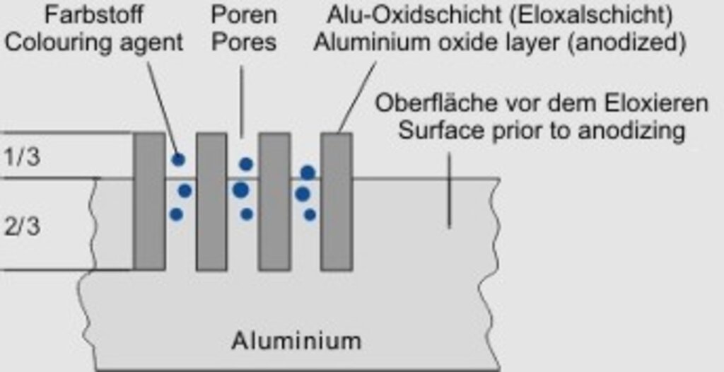
Abb. 1
During the anodizing process the oxide layer grows forming columns to about 2/3 within the bas material; 1/3 builds up externally which must be taken into account in (see fig. 1).
The achievable layer-thickness is up to 30 µm, layers that are thicker than this generally begin to chalk and are unusable. Higher layer thicknesses are possible with the hard-anodizing process. Information on this can be found in the corresponding chapter.
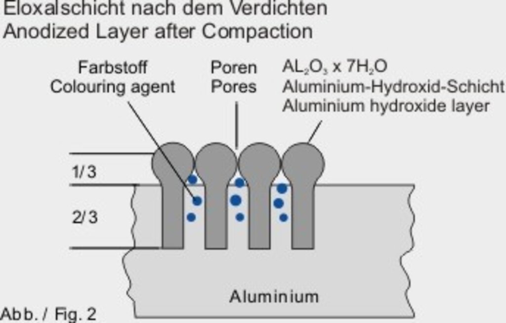
Abb. 2
In order to make the anodized layer weatherproof and to close the absorbent pores it is necessary to carry out a so-called “compaction”.
This will be reached by a chemical conversion of the anodized layer (aluminium oxide) into a large voluminous aluminium hydroxide (see fig. 2). Simultaneously, thus an effloresce of dyed items will be prevented.
Surface Characteristics and Faults
Anodizing faults (e.g. chalking, chipping, offshade dying or insufficient layer thickness) can normally be eliminated by de-anodizing and re-anodizing. As with pickling there is a removal of material which is 15-25 µm depending on the layer-thickness. Therefore, in such a case extreme fit sizes of precision parts need to be covered beforehand.
Generally, surface characteristics and faults caused by extrusion, metallurgical or corrosion problems cannot be corrected by anodizing.
Due to the semi-transparency of the coating, decorative anodizing is limited, because the alloy separations and other inhomogeneities, which disturb the structures and become visible due to the machining, can not be detected before.
Here, only a few of the large number of possible structure and surface defects are described, which have given reasons for complaints frequently. However, because of their cause they are unavoidable. Some recommendations for decorative anodizable aluminium alloys are given by the according DIN-standard.
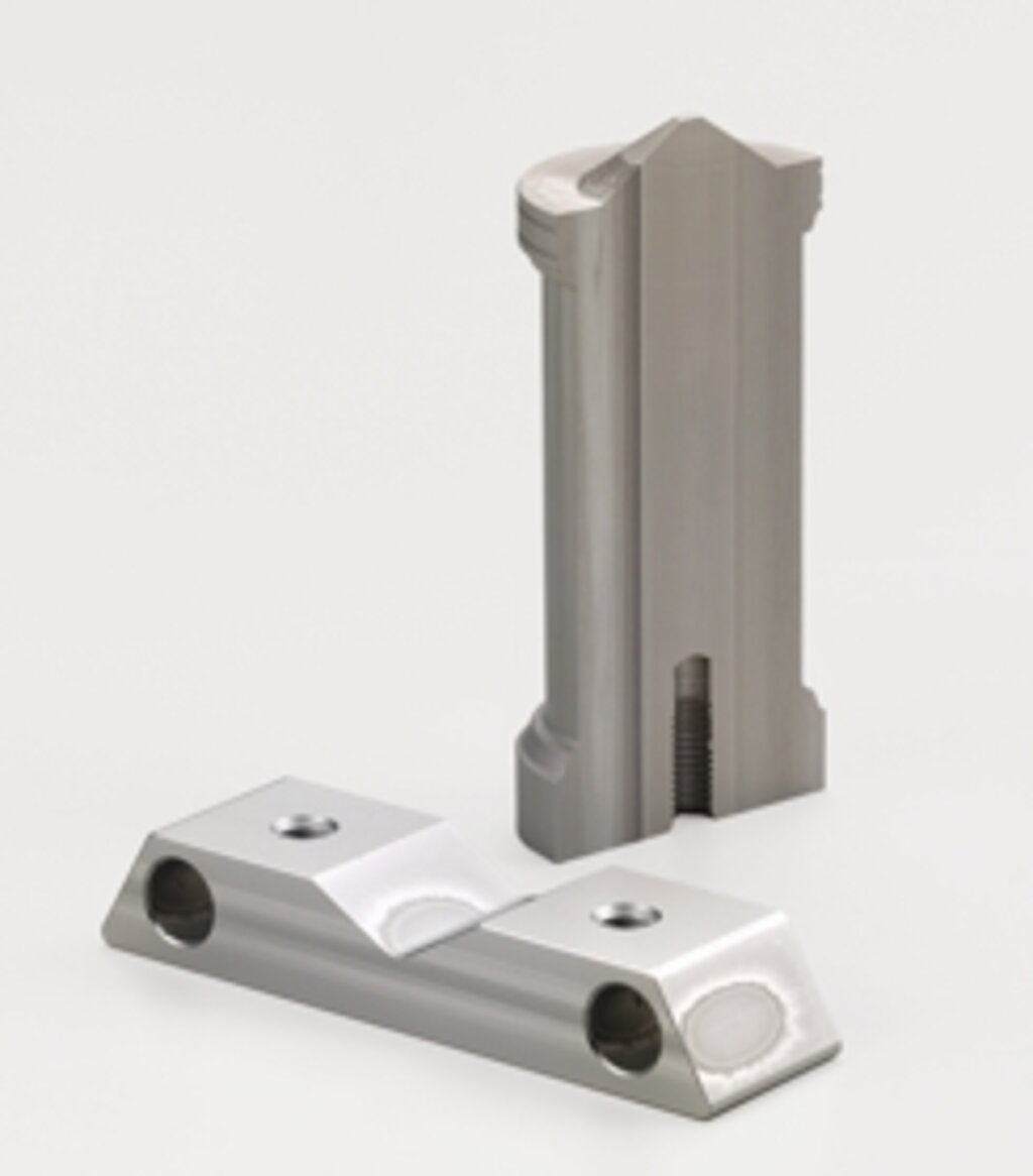
Abb. 3.0
Naturfarbig eloxierte Oberfläche
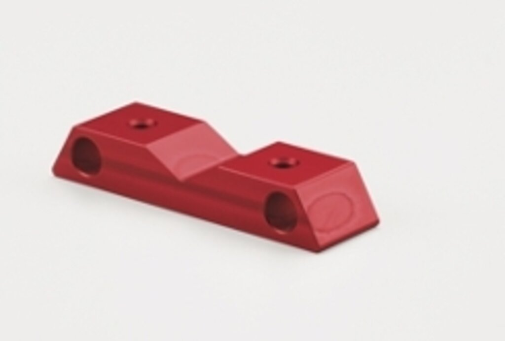
Abb. 3.1
Dasselbe Teil wie in Abb. 3.0; wieder enteloxiert, erneut eloxiert und rot gefärbt
Transverse Seam/Two Wax
The two figured items (Figure 3.0) made of extruded round and rectangular aluminium sections show stripes of dark discolouration after anodizing, which were previously not visible on the rough part.
Such faults can typically occur during the manufacturing of profiles by extruding block-on-block in the inner and outer areas of the material. This effect (inhomogeneity) cannot be covered (see fig. 3.1) even by dying the anodized layer. For this purpose, the only remedy is to cut out this profile area in the extrusion die on request of the customer.
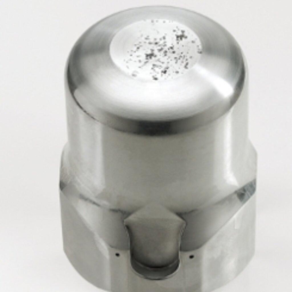
galvanische Korrosion
Contact Corrosion
(galvanic corrosion) with the typical pitting or the formation of indentations as shown in the adjacent figure, occurs particularly on components made of the highly alloyed AlCu-group. A frequent cause is the contact of the component in a damp condition with a metallic surface after it has been machined mechanically. In this way a voltage potential is formed which slowly begins to break down the unprotected surface electrolytically. This type of corrosion is difficult to see in the unanodized condition.
Packing Corrosion
due to wrapping paper containing sodium bicarbonate in a damp atmosphere, is similar to the chemical process that takes place when pickling (matting) in sodium hydroxide solution and likewise causes similar surface defects. Both types of corrosion emerge clearly after anodizing and can only be resolved by mechanical surface removal.
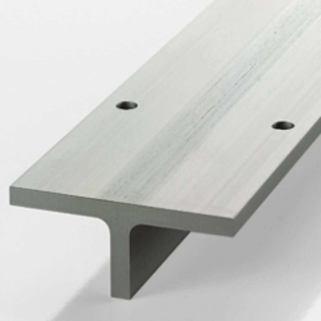
Stegabzeichnungen
Web Marks
on the profile in the direction of extrusion after anodizing are a consequence of the connection bridges in the mould. There are many causes, ranging from the mould design and the temperature to the alloy composition and the speed of extrusion. Generally, it is not possible to carry out any rework on these.
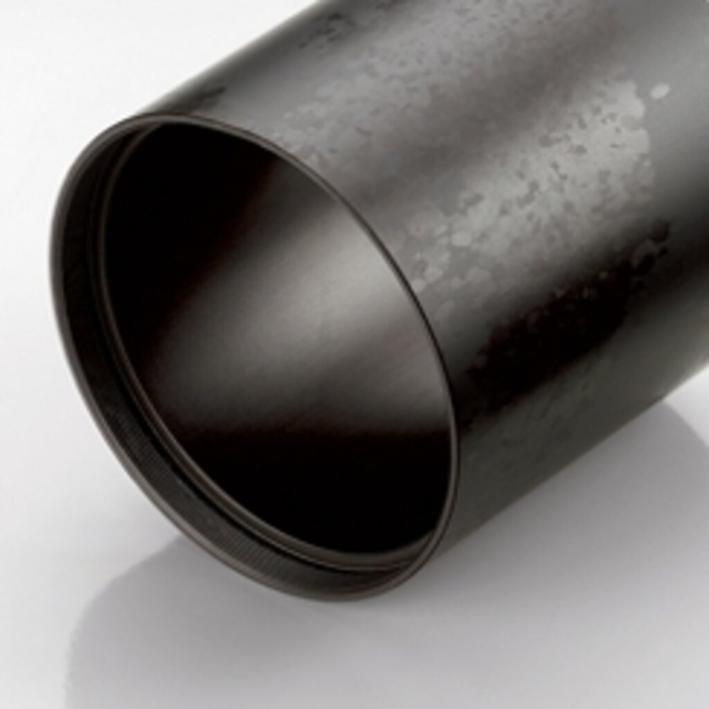
Grobkorn
Coarse Grains
can be seen in terms of various sized spottings after pickling. This effect can extend completely at thin wall thicknesses. On thick cross-sections it can be recognized in the form of individual grains. The edges of coarse grains can be found directly on the surface (see Fig.) or close underneath. Only such defects on the surface can be resolved by material removal and subsequent decorative anodizing. The causes lie both in the alloy composition and in the extrusion process.

Wellenmuster
Wavelike Samples
on blank sheets, which remind of sandy waves in tidelands, result by expanding oxides into the surface of the raw pellet. Minimum ovalities of the press rolls may cause similar effects in the structural condition. This surface fault will be clearly visible only after anodizing and can normally not be eliminated by grinding or heavy pickling. A reliability can only be provided by ordering blank sheets in anodizing quality.
Aluminium-Material-Datasheets
The recommendation for the anodizabilty of aluminium alloys aside is given according to the DIN data sheets.
EQ = Anodizing quality acc. to DIN 17611
• = Wear-resistant surfaces possible by hardcoating
– = at missing characteristics no further literature references available
Signification of characteristics:
1 = excellent
2 = good
3 = satisfactory
4 = inadequate
5 = not recommendable
6 = unsuitable
Anodizability:
D = decorative coating
S = protective coating
HC = hardanodizing coating
Quelle:
Aluminium-Material-Datasheets
Aluminium-Verlag
Forgeable alloys DIN EN 573-3
| EU-Standard | DIN 1725-1 |
Designation | Anodizability | |||
| new | former | D | S | HC | ||
| EN AW-1050A | 3.0255 | Al99,5 | – | 2 (EQ=1) | 1 | – |
| EN AW-1070A | 3.0275 | Al99,7 | – | 1 | 1 | – |
| EN AW-1080A | 3.085 | Al99,8(A) | – | 1 | 1 | – |
| EN AW-1098 | 3.0385 | Al99,98 | Al99,98R | – | – | – |
| EN AW-1200 | 3.0205 | Al99,0 | – | 3 | 1 | – |
| EN AW-1350A | 3.0257 | EAl99,5(A) | E-Al | – | – | – |
| EN AW-2007 | 3.1645 | AlCu4PbMgMn | AlCuMgPb | – | 5 | • |
| EN AW-2011 | 3.1655 | AlCu6BiPb | AlCuBiPb | 6 | 5 | • |
| EN AW-2014 | 3.1255 | AlCu4SiMg | AlCuSiMn | 6 | 3 | – |
| EN AW-2017A | 3.1325 | AlCu4MgSi(A) | AlCuMg1 | 6 | 2 | – |
| EN AW-2024 | 3.1355 | AlCu4Mg1 | AlCuMg2 | 6 | 2 | – |
| EN AW-2117 | 3.1305 | AlCu2,5Mg | AlCu2,5Mg0,5 | – | – | – |
| EN AW-3003 | 3.0517 | AlMn1Cu | AlMnCu | 4 | 1 | – |
| EN AW-3004 | 3.0526 | AlMn1Mg1 | – | 4 | 1 | – |
| EN AW-3005 | 3.0525 | AlMn1Mg0,5 | – | 4 | 1 | – |
| EN AW-3103 | 3.0515 | AlMn1 | – | 4 | 1 | – |
| EN AW-3105 | 3.0505 | AlMn0,5Mg0,5 | – | – | – | – |
| EN AW-3207 | 3.0506 | AlMn0,6 | – | – | – | – |
| EN AW-5005 | – | AlMg1(B) | – | 3 | 1 | – |
| EN AW-5005A | 3.3315 | AlMg1(C) | AlMg1 | 2 (EQ=1) | 1 | – |
| EN AW-5019 | 3.3555 | AlMg5 | – | 4 | 1 | – |
| EN AW-5049 | 3.3527 | AlMg2Mn0,8 | – | 4 | 2 | – |
| EN AW-5041A | 3.3326 | AlMg2(B) | AlMg1,8 | – | – | – |
| EN AW-5052 | 3.3523 | AlMg2,5 | – | 2 | 1 | – |
| EN AW-5083 | 3.3547 | AlMg4,5Mn0,7 | AlMg4,5Mn | 4 | 2 | – |
| EN AW-5086 | 3.3545 | AlMg4 | AlMg4Mn | 3 | 1 | – |
| EN AW-5182 | 3.3549 | AlMg4,5Mn0,4 | AlMg5Mn | – | – | – |
| EN AW-5241 | 3.3525 | AlMg2 | AlMg2Mn0,3 | 4 | 1 | – |
| EN AW-5454 | 3.3537 | AlMg3Mn | AlMg2,7Mn | 4 | 2 | – |
| EN AW-5754 | 3.3535 | AlMg3 | – | 2 (EQ=1) | 1 | – |
| EN AW-6005A | 3.3210 | AlSiMg(A) | AlMgSi0,7 | 2 | 1 | – |
| EN AW-5012 | 3.0615 | AlMgSiPb | AlMgSiPb | bis 10µm | 3 | • |
| EN AW-6060 | 3.3206 | AlMgSi | AlMgSi0,5 | 1 (EQ) | 1 | – |
| EN AW-6061 | 3.3211 | AlMg1SiCu | – | 3 | 1 | – |
| EN AW-6082 | 3.2315 | AlSi1MgMn | AlMgSi1 | 3 | 1 | – |
| EN AW-6101B | 3.3207 | EAlMgSi(B) | E-AlMgSi0,5 | – | – | – |
| EN AW-7020 | 3.4335 | AlZn4,5Mg1 | AlZn4,5Mg1 | 3 | 2 | – |
| EN AW-7022 | 3.4345 | AlZn5Mg3Cu | AlZnMgCu0,5 | 6 | 2 | – |
| EN AW-7075 | 3.4365 | AlZn5,5MgCu | AlZnMgCu1,5 | 6 | 3 | – |
| EN AW-8011A | 3.0915 | AlFeSi(A) | AlFeSi | – | – | – |
Casting alloys DIN EN 1706 |
||||||
| EU-Standard | DIN 1725-1 |
Designation | Anodizability | |||
| new | former | D | S | HC | ||
| EN AC-21000 | 3.1371 | G-/GK-/GF-AlCu4MgTi | – | – | 3 | – |
| EN AC-21100 | 3.1841 | G-/GK-AlCu4Ti | – | – | 3 | – |
| EN AC-42100 | 3.2371 | G-/GK-/GF-AlSi7Mg0,3 | – | – | 4 | – |
| EN AC-42200 | – | AlSi7Mg0,6 | – | – | 4 | – |
| EN AC-43000 | 3.2381 | G-/GK-AlSi10Mg(a) | – | – | 5 | – |
| EN AC-43200 | 3.2383 | G-/GK-AlSi10Mg(Cu) | – | – | 5 | – |
| EN AC-43300 | 3.2373 | G-/GK-/GF-AlSi9Mg | – | – | 5 | – |
| EN AC-43400 | 3.2382 | G-/GK-/GF-AlSi10Mg(Fe) | – | – | 5 | – |
| EN AC-44000 | 3.2211 | G-/GK-AlSi11 | – | – | 5 | – |
| EN AC-44200 | 3.2373 | G-/GK-AlSi12(a) | – | – | 5 | – |
| EN AC-4300 | 3.2582 | GD-AlSi12(Fe) | – | – | 5 | – |
| EN AC-45000 | 3.2151 | G-/GK-AlSi6Cu4 | – | – | 4 | – |
| EN AC-46000 | 3.2163 | GD-AlSi9Cu3(Fe) | – | – | 5 | – |
| EN AC-46200 | 3.2163 | G-/GK-AlSi8Cu3 | – | – | 5 | – |
| EN AC-47000 | 3.2583 | G-/GK-AlSi12(Cu) | – | – | 5 | – |
| EN AC-47100 | 3.22982 | GD-AlSi12Cu1(Fe) | – | – | 5 | – |
| EN AC-48000 | – | GK-AlSi12CuNiMg | – | – | 5 | – |
| EN AC-51100 | 3.3541 | G-/GK-/GF-AlMg3(a) | – | – | 1 | – |
| EN AC-51200 | 3.3292 | GD-AlMg9 | – | – | 2 | – |
| EN AC-51300 | 3.3561 | G-/GK-AlMg5 | – | – | 1 | – |
| EN AC-51400 | 3.3261 | G-/GK-AlMg5(Si) | – | – | 2 | – |
| EN AC-71000 | – | AlZn5Mg | – | – | 2 | – |
| Casting alloys DIN EN 1725 (replaced by DIN EN 1706) | ||||||
| Eurostandard | DIN 1725-1 |
Designation | Anodizability | |||
| new | former | D | S | HC | ||
| – | 3.2581 | G-/GK-AlSi12 | – | 6 | 4 | 4 |
| – | 3.2583 | G-/GK-AlSi12(Cu) | – | 6 | 4 | 4 |
| – | 3.2381 | G-/GK-AlSi10Mg | – | 4 | 3 | 4 |
| – | 3.2383 | G-/GK-AlSi10Mg(Cu) | – | 6 | 4 | 4 |
| – | 3.2163 | G-/GK-AlSi9Cu3 | – | 6 | 6 | 4 |
| – | 3.2153 | G-/GK-AlSi6Cu4 | – | 6 | 6 | 4 |
| – | 3.2211 | G-/GK-AlSi11 | – | 6 | 4 | 4 |
| – | 3.2373 | G-/GK-AlSi9Mg | – | 6 | 4 | 4 |
| – | 3.2371 | G-/GK-/GF-AlSi7Mg | – | 6 | 4 | 4 |
| – | 3.1841 | G-/GK-AlCu4Ti | – | 6 | 5 | 4 |
| – | 3.1371 | G-/GK-/GF-AlCu4TiMg | – | 6 | 5 | 4 |
| – | 3.3541 | G-/GK-/GF-AlMg3 | – | 1 | 1 | 1 |
| – | 3.3241 | G-/GK-/GF-AlMg3Si | – | 2 | 1 | 1 |
| – | 3.3561 | G-/GK-AlMg5 | – | 1 | 1 | 1 |
| – | 3.3261 | G-/GK-AlMg5Si | – | 2 | 1 | 1 |
| – | 3.2341 | G-/GK-AlSi5Mg | – | 4 | 2 | 3 |
| – | 3.2163 | GD-AlSi9Cu3 | – | 6 | 6 | 4 |
| – | 3.2982 | GD-AlSi12(Cu) | – | 6 | 6 | 4 |
| – | 3.2582 | GD-AlSi12 | – | 6 | 5 | 4 |
| – | 3.2382 | GD-AlSi10Mg | – | 6 | 4 | 4 |
| – | 3.3292 | GD-AlMg9 | – | 4 | 2 | 2 |
Temas
Rohde AG
Industriestrasse 9
D - 37176 Nörten-Hardenberg
Tel.: +49 (0) 5503 9860-0
Fax: +49 (0) 5503 9860-11
info@rohde-technics.com